Non Linear Spring, 2 Node
Introduction:
(If you want to skip this intro, click here)
The Usfos 2 Node Non Linear Spring element is a beam element, which gets it's properties in the 6 degrees of freedom by the P_d curves referred to through the material reference MREF. All 6 degrees of freedom may have different properties, and refrerring to a P_D curve with ID=0, the actual degree of freedom gets no stiffenss. The properties defined for the non linear spring to ground are referred to the local beam coordinate system similar to what's the case for "ordinary" beams.
The non linear spring has following properties, only one (bold) is mandatroty, the rest are optional:
Non linear Spring behaviour:
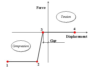
Properties of the spring are defined by discrete points as shown in the example below. (If pure linear behaviour is required, specify a straight P_d curve).
The curves are always defined from the very left side (3'rd qudrant) towards right (1'st quadrant) as indicated above. The curve may have any shape, and different behaviour in tension (1'st quadrant) and compression (3'rd quadrant) is possible. F ex: A simple contact spring is obtained by specifying ~Zero tension capacity and relatively high stiffenss in compression (too high stiffness might cause numerical problems!).
Simply Supported Beam with extra support (50 mm gap) at midpoint
=> Usfos Control File
=> Structural File
=> Animation
=> Animation 3D
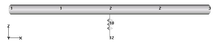
A simply supported beam spanning from node 1 to node 3 is modelled with two "ordinary" beam elements. At the midpoint (node 2) a 2 node non linear spring is attached. The other end of the spring is fully fixed (in node 12). The beam is loaded at node 2, first with a vertical (downwards) load of 5 MN, and thereafter the load is reversed (trying to apply 5 MN upwards too).
The spring is modelled with a 50 mm gap as indicated in the P_d curve above. Teh Spring gives no resistance util 50 mm compression is obtained. Then, the spring becomes relative rigid, and will give a good support of the beam midpoint.
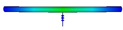
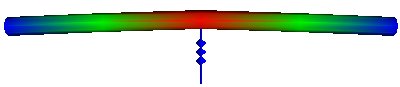
Due to the extra support at the beam midpoint, it's possible to apply 5 MN load downwards without damaging the beam (see beam utilization at load level 5 MN below).
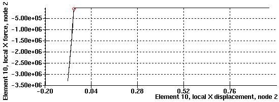
When the load is reveresed, no similar support is obtained, and the beam yields for a load level ~3 MN (see image below).
The force in the support (contact) spring documents the actual spring behaviour, and the Element Displacment versus Element Force, Node2 is shown below (Xfos: Results/History Plot).